

Chapters · Chapter 8 of 8
Model your machine's hardware
Bind detected hardware to logical roles, verify its connections, and inspect registered software.
Joining here?
Stop Pinman, run this command, then start Pinman again. It rebuilds the sample project up to this point, discarding any work you have already done in it.
pinman tutorial goto devicesWhat to expect#
Pinman has tracked files, Windows Registry values, and live settings on your workstation. Some of that state belongs to physical devices whose Windows identifiers can change when they are disconnected, moved, or replaced. The Machine page gives Pinman a stable model of the hardware behind those settings.
Pinman calls a physical machine or module a Box. Within a Box, logical roles describe what its devices do, bindings connect those roles to the hardware Windows detects, and connector assignments record where the devices belong. Profiles and status checks can then refer to a role instead of relying on one Windows device identifier.
The hardware shown in this chapter is your own. You will add one display to your Box, but you will not change its settings or disconnect anything.
Steps#
Discover what is connected#
- From the main navigation, open Machine.
- Select Detect Devices and wait for the scan to finish.
Pinman creates or updates a Box for this machine and inventories the hardware Windows reports.
Detection is the starting point. It tells Pinman what is connected now, including the identifiers and properties Windows assigned to each device. Managing the workstation begins when you tell Pinman which of those devices matter and what each one does.
Add a display to your Box#
- Expand Unassigned Devices and, if the device filters are shown, select Display.
- Select a connected display to expand its row. Select the button labeled Add to followed by your Box name.
- The display moves into your Box. Close the Unassigned Devices list.
- In your Box, expand the display's row to inspect its information, including resolution, connector, and current status checks.
Give the display a stable role#
- On the display's row, there is a blue info-icon button rowards the right. Select it to open Device details side panel.
Here you can assign roles to the device. Available roles are domain-specific and defined by the project's schema. The Basics schema defines three device roles: Program Display, Reference Display, and Program Audio. Assign this monitor as Program Display.
- Under Roles, select Program Display, then select Save Roles and close the panel.
The following screenshot previews the result after I also assigned the
Program Display role and checked the monitor's status. The expanded panel
shows its connector (DVI-1), Windows identifier (DISPLAY5), driver status,
and other checks. You will assign the role and run the status check next.
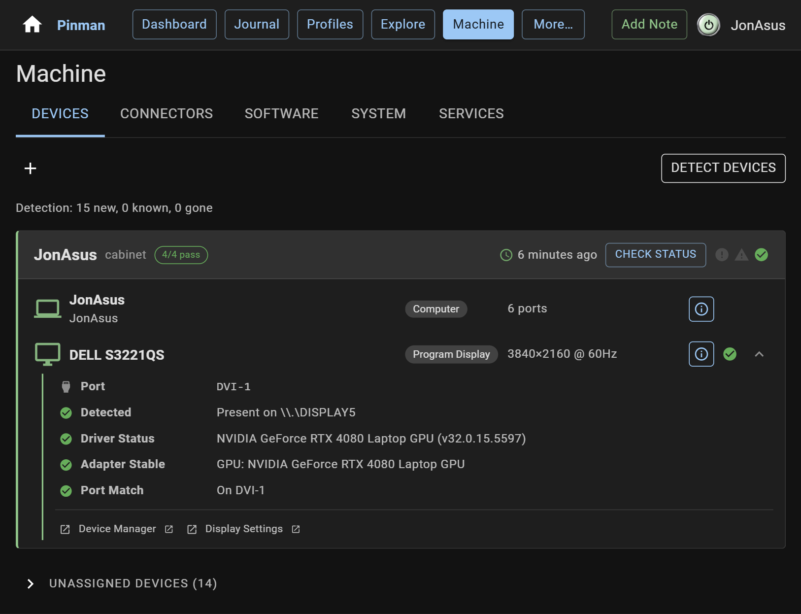
Program Display is a logical role defined by the Basics schema. It acts like a variable: a Profile that adjusts resolution can target Program Display, while the Box resolves that role to the monitor assigned on this machine. Assigning the role creates bindings to detected properties such as the Windows identifier, dimensions, and position.
For a video workstation, the same Box could distinguish a program display from a reference display and assign Program Audio to the usual sound output. If a monitor or audio device is later replaced, the role can stay the same while its physical assignment changes.
Record and check the connection#
- Open the Connectors tab and find the display you assigned under Video Connectors.
- Hover over that row and select Set as expected device (the pin icon). Pinman now expects that display on its current connector.
- Return to Devices and select Check Status on your Box. Expand the assigned display's row to see the presence and connection checks Pinman can perform.
In the following screenshot, I have pinned my external Dell monitor to the
DVI-1 port. The green dot confirms that the expected monitor is present. If it
were disconnected, the row would show a red status icon; if a different device
were connected there, it would show a warning.
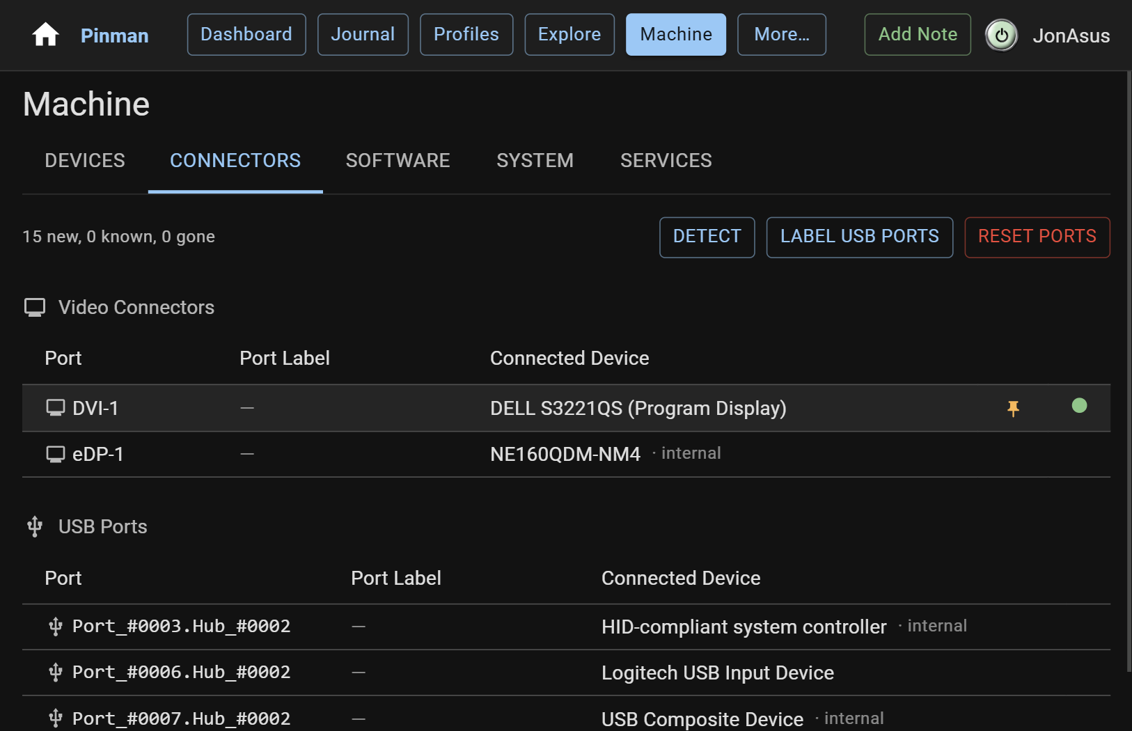
This is the difference between inventory and management. If the display is later missing or connected differently, the Box can report that the expected setup is not present. After changing or hot-plugging devices, you can check the Box and then apply the Profile intended for the connected arrangement.
The same idea applies to USB capture devices and controllers. If a workstation is transported and a device is plugged into a different USB port, Windows may give it a different identifier. An expected connector assignment gives Pinman a specific mismatch to report instead of leaving an application to fail without explaining why.
See how software fits the model#
Hardware is only part of the Machine page. Pinman also knows which tracked files and settings belong to each program through their Program tags.
The Basics schema registers the fictional Basics Screen Recorder application. The Software tab confirms that Pinman found it and shows its Production:Recording zone. The schema also tags the recorder's tracked files and settings with this program, allowing Pinman to associate configuration with the application that owns it instead of relying only on its location on disk.
- Open the Software tab and select Detect Software.
- Expand Basics Screen Recorder and open Program details. Confirm that it is Installed and assigned to the Production:Recording zone.
The details panel shows the tutorial application's detected state and the metadata supplied by its schema entry.
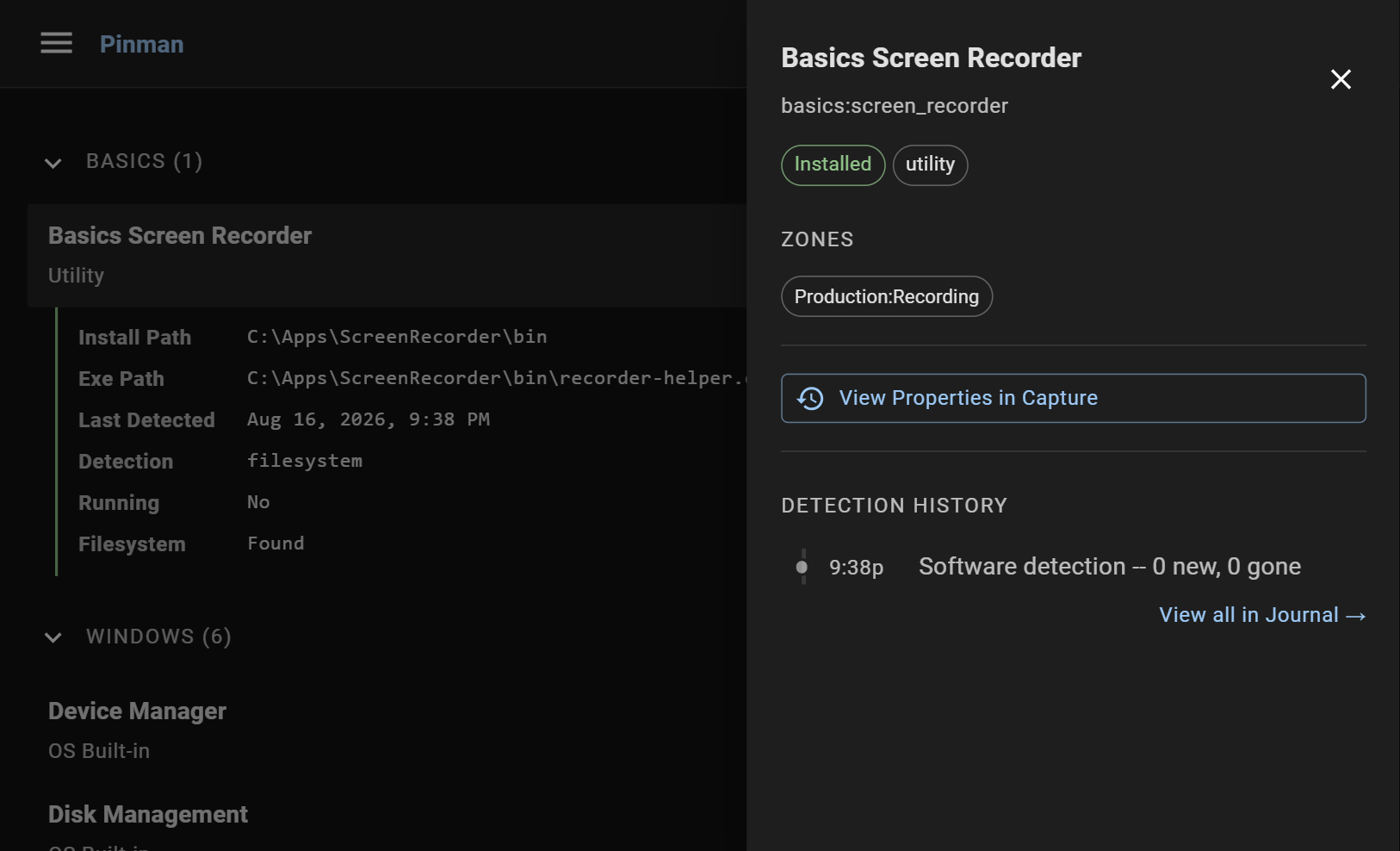
For real software, a catalog entry can also provide a command that launches the program or opens its configuration tool. When a setting cannot, or should not, be written directly by Pinman, Guided Manual Mode can use that integration to walk you through the change.
What we did#
You detected the machine's hardware, assigned a physical monitor to the logical Program Display role, recorded its expected connector, and checked the Box's status. You also detected a registered program and inspected its schema-defined metadata.
The scan established what is connected. The Box, role, bindings, and connector assignment made that information useful for Profiles and ongoing status checks.
Where to go from here#
That's the whole loop: capture a known configuration, refresh to see what changed, explain it in the Journal, and turn configurations worth keeping into Profiles. The same pattern can manage different workstation arrangements, development and release modes, or test and production environments.
The Basics sample project is a sandbox, so you can continue experimenting with
its files and Profiles. To start over, run pinman tutorial install basics. To
jump directly to any chapter, use its Start from this step command.
To learn more about what Pinman can do, how it works, and how to author your own schemas and kits, visit the Pinman documentation. More tutorials will be added in the future.
Instructions#
-
From the main navigation, open Machine.
-
Select Detect Devices and wait for the scan to finish.
-
Expand Unassigned Devices and, if the device filters are shown, select Display.
-
Select a connected display to expand its row. Select the button labeled Add to followed by your Box name.
-
The display moves into your Box. Close the Unassigned Devices list.
-
In your Box, expand the display's row to inspect its information, including resolution, connector, and current status checks.
-
On the display's row, there is a blue info-icon button rowards the right. Select it to open Device details side panel.
-
Under Roles, select Program Display, then select Save Roles and close the panel.
-
Open the Connectors tab and find the display you assigned under Video Connectors.
-
Hover over that row and select Set as expected device (the pin icon). Pinman now expects that display on its current connector.
-
Return to Devices and select Check Status on your Box. Expand the assigned display's row to see the presence and connection checks Pinman can perform.
-
Open the Software tab and select Detect Software.
-
Expand Basics Screen Recorder and open Program details. Confirm that it is Installed and assigned to the Production:Recording zone.